Introduction
This is a how-to guide for replacement of 1-18976 Hyplex Prime Major Repair Kit from Accustream.
-
-
Refer to original equipment manufacturer's safety and maintenance instructions. Failure to do so could result in injury or death.
-
Always remove all stored energy and lock out equipment before beginning any work.
-
-
-
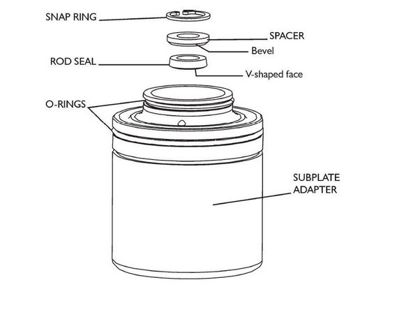
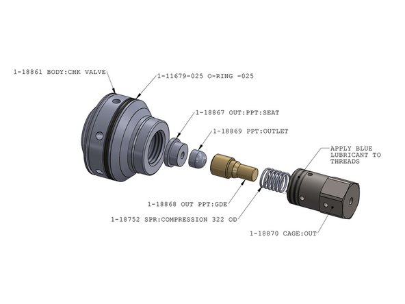
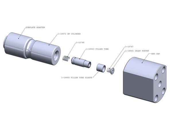
Exploded view with BOM
-
-
-
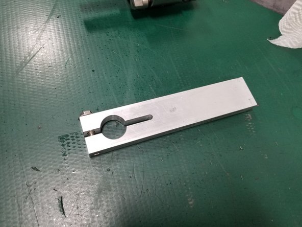
Pressure Loading tool
-
Check valve clamp tool
-
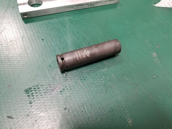
Plunger removal socket
-
-
-
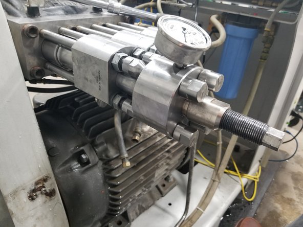
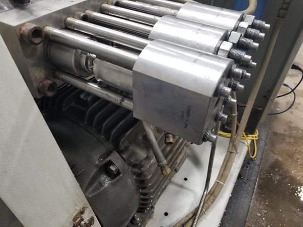
Remove inlet water hoses from the bottom of the end cap
-
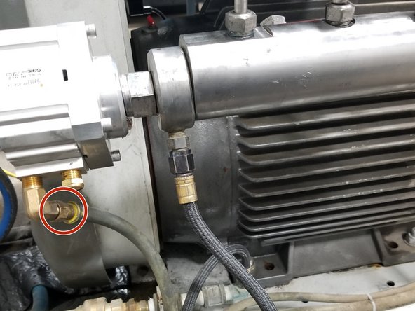
Disconnect air line from actuator
-
Disconnect PCV drain line
-
-
-
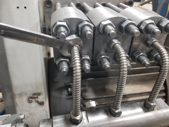
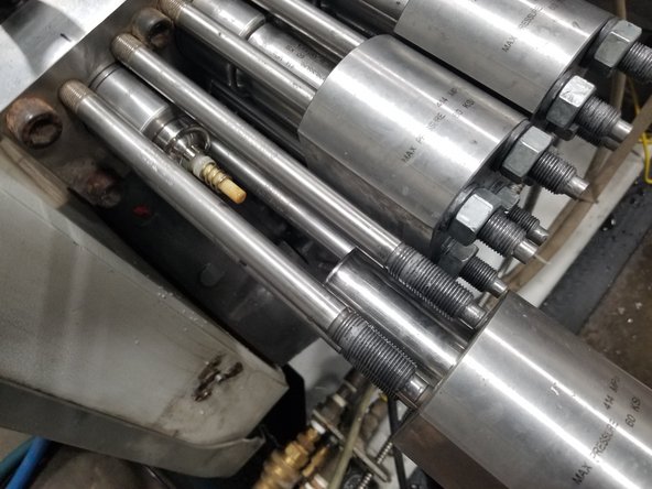
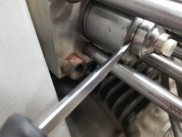
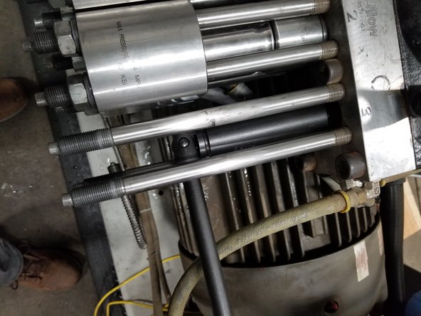
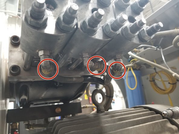
Remove high-pressure tube from manifold using a 13/16" open end wrench
-
Remove high-pressure inlets from all end caps using 13/16" open end wrench while supporting the manifold
-
-
-
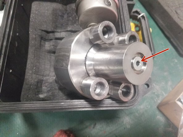
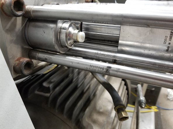
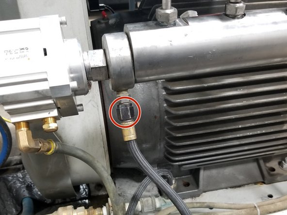
Ensure oil is full. Open the 3/16" hex screw located on the contact face to check/fill using ATF fluid
-
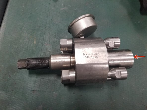
Ensure pressure loading tool screw is fully retracted
-
Ensure piston is fully retracted
-
-
-
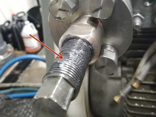
Keep screw lubricated with MOLYKOTE® BR-2 Plus or similar
-
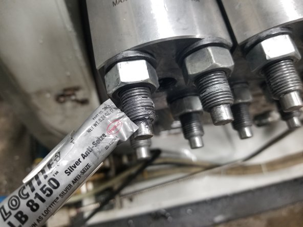
Wipe stud threads clean and apply Loctite 8150 anti-seize (#1-18750)
-
-
-
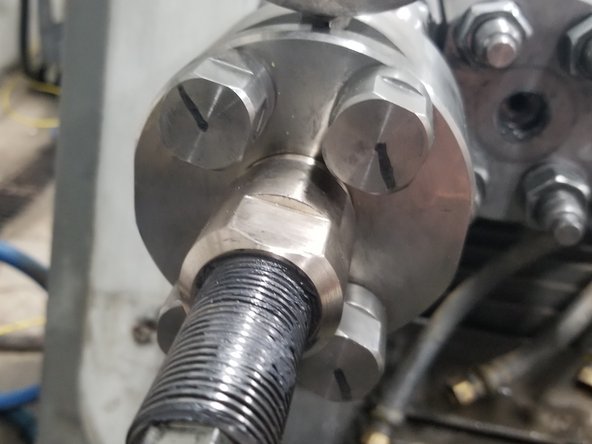
Attach pressure loading tool to each set of studs, rotating each tool stud by hand until tight
-
Once snug, back out the tool studs 1/4 turn. Place a radial line with a permanent marker to make this easier to see
-
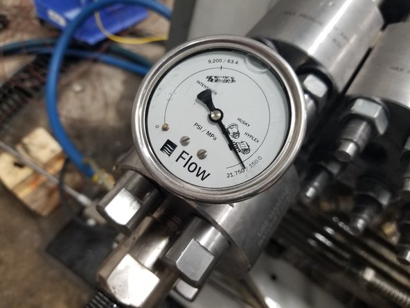
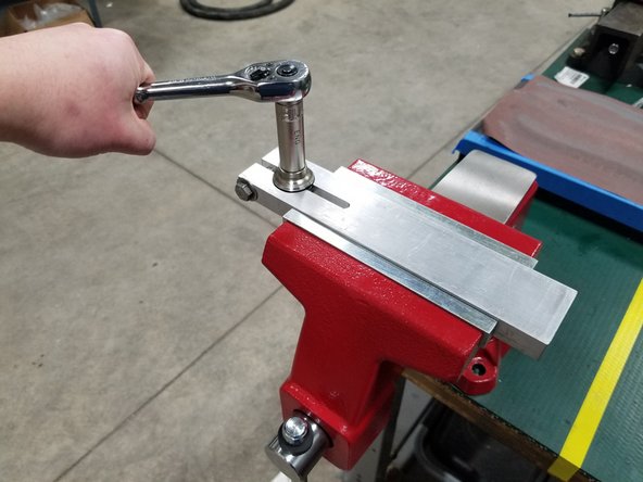
Use a 3/4" (19mm) ratcheting socket to pressurize the tool by rotating screw clockwise. Pressurize per manufacturers recommended gauge pressure
-
-
-
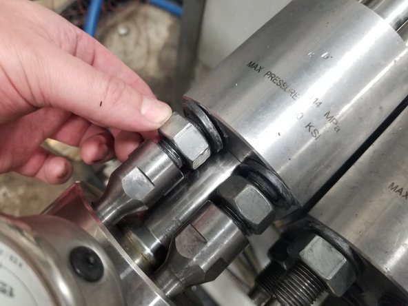
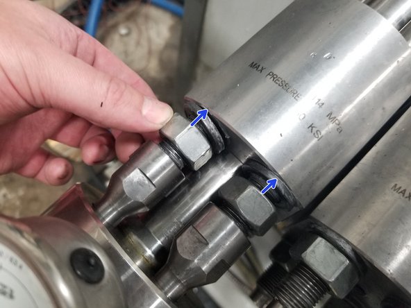
While tool is pressurized, loosen the four nuts a few turns by hand
-
Turn the 3/4" socket counter-clockwise to reduce the pressure in the tool
-
Back off each of the four tool studs and remove the pressure loading tool
-
-
-
Remove the fours nuts and washers
-
Carefully slide the end cap off, being careful not to lose any of the high-pressure components
-
-
-
HP cylinder and filler tube may come out with end cap
-
Use a screwdriver to remove seal carrier, if necessary
-
-
-
Remove subplate adapter (gently pry groove if necessary)
-
Remove snap ring and rod seal, install new rod seal (1-11993) and snap ring (1-18745). Inspect and replace spacer with bevel down
-
-
-
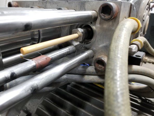
Use plunger removal socket and ratchet to remove the plunger retaining nut
-
Rotate belt/crank to extend plunger, if necessary
-
Replace with new plunger and spring. Torque plunger nut to 20 ft-lb (27 N-m).Be careful not to contact the plunger
-
-
-
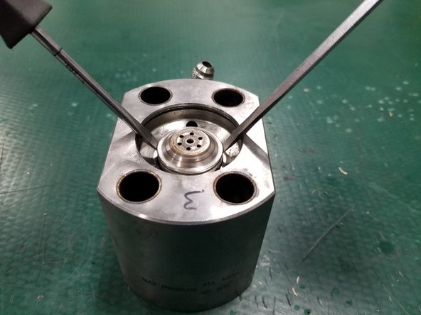
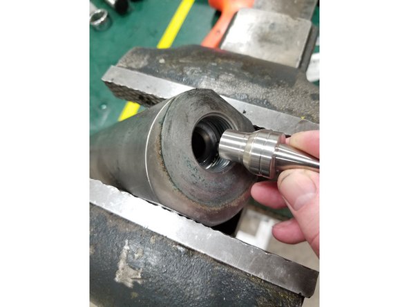
Carefully lift the check valve assembly using two flathead screwdrivers in the groove on the check valve body
-
-
-
Insert check valve body clamp tool into bench vise
-
Use a 9/16" socket to tighten the clamp onto the check valve body
-
Remove the Outlet Cage using the 9/16" socket
-
Inspect outlet cage. Replace all other items
-
Re-install outlet cage:
-
Apply blue lubricant to outlet cage threads and insert new internal components
-
Carefully thread cage into check valve while maintaining alignment of internal components
-
Torque outlet cage to 30 ft-lb (41 N-m)
-
-
-
Install new End Cap o-ring
-
Apply high-vac grease (1-11447) to both o-rings
-
Insert check valve assembly into end cap
-
-
-
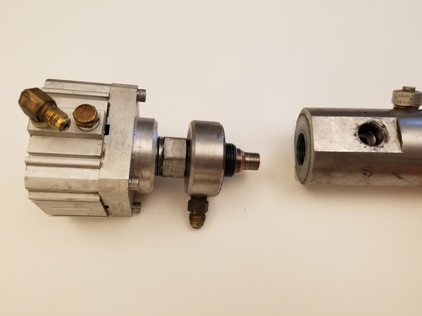
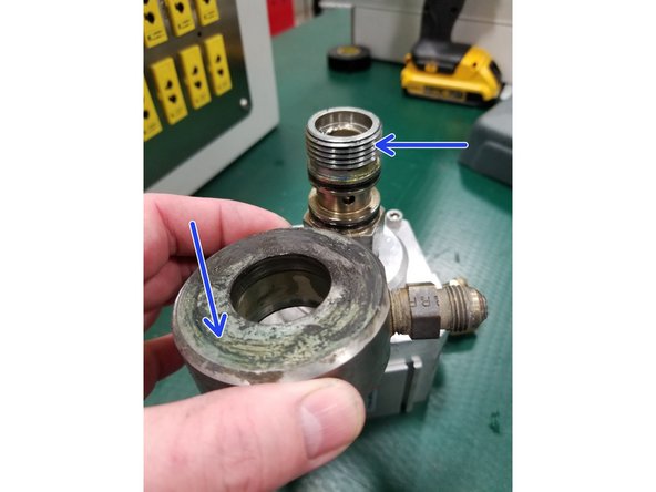
With manifold removed from pump, place manifold in a heavy bench vise
-
Remove the PCV body using a 1-1/4" (32 mm) wrench
-
-
-
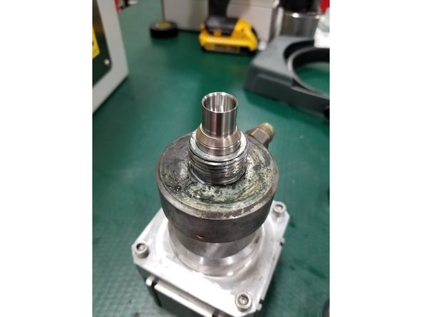
Apply blue lubricant to threads and both faces of the PCV adapter
-
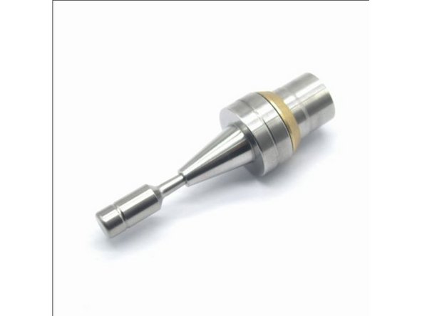
Install new PCV Ring onto new PCV Seat, and insert PCV Poppet into seat. Insert PCV assembly into PCV body
-
Thread manifold onto PCV Adapter. Torque to 190 ft-lb (258 N-m)
-
-
-
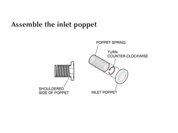
Attach 1-18747 spring to 1-18865 Inlet Poppet
-
-
-
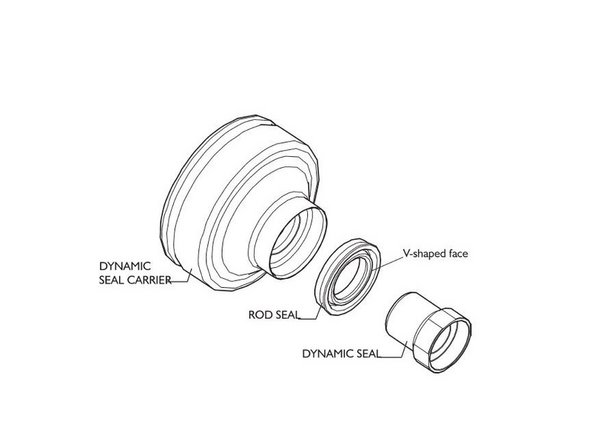
Insert dynamic seal and rod seal into new seal carrier (slight pressure is required to seat dynamic seal)
-
Install rebuilt subplate adapter
-
Slide seal assembly over plunger up to subplate adapter
-
-
-
Insert new o-ring into HP Cylinder. Apply a small amount of high-vac grease to o-ring
-
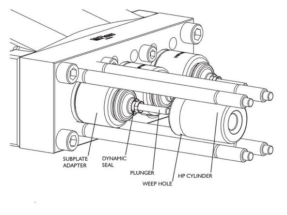
Carefully slide HP cylinder over the seal carrier, keeping the weep hole facing down
-
Insert 1-18748 spring into Filler Tube. Slide filler tube sleeve onto filler tube, insert poppet assembly into filler tube
-
Insert assembly into HP Cylinder
-
-
-
Slide End Cap onto tie rods and align with HP Cylinder
-
Place washers and nuts on tie rods, hand tighten until snug
-
Attach and pressurize the pressure loading tool. Tighten nuts by hand until they are snug against the end cap
-
Remove pressure from pressure loading tool
-
Repeat for all three lines
-
-
-
Apply blue lubricant to high-pressure fittings
-
Torque high-pressure glands to: 40 ft-lbs (54 N-m)
-
Attach manifold/high-pressure glands, air line, PCV drain line, and inlet lines
-
-
-
-
When complete, unlock system and restore energy
-
Start pump and check for any leaks
-