
Tools
No tools specified.
Parts
-
-
Turn power OFF to AccuStream pump and at main breaker supplying pump.
-
All lockout/tagout procedures must be followed. Failure to do so could result in serious injury or death.
-
-
-
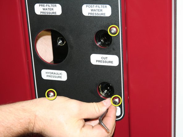
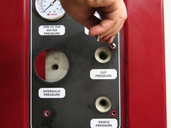
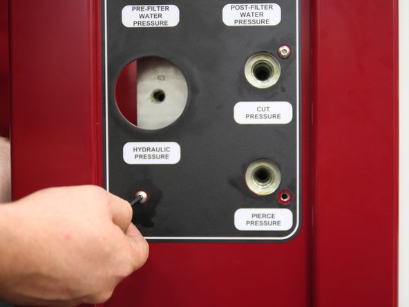
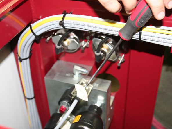
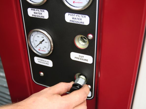
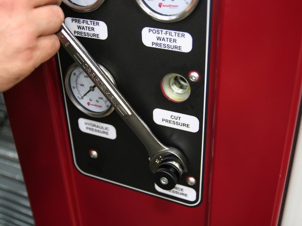
Remove hydraulic pressure gauge.
-
Remove control knobs from front of manifold.
-
Label control knots "Cut" and "Pierce", respectively, to identify for re-installation.
-
-
-
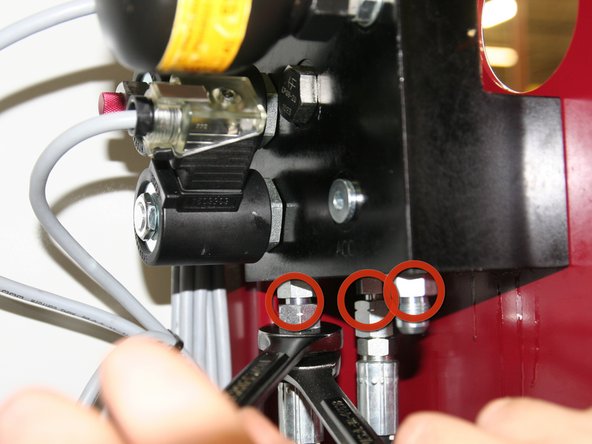
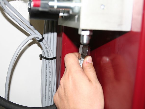
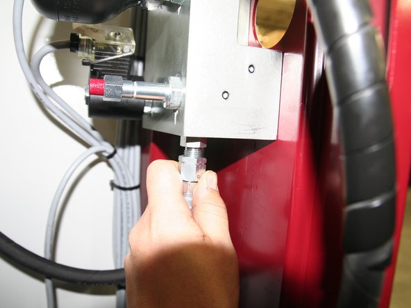
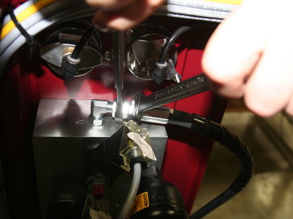
Disconnect hoses and fittings from bottom of old control manifold.
-
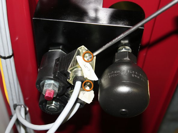
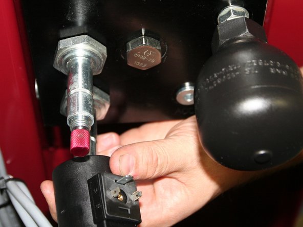
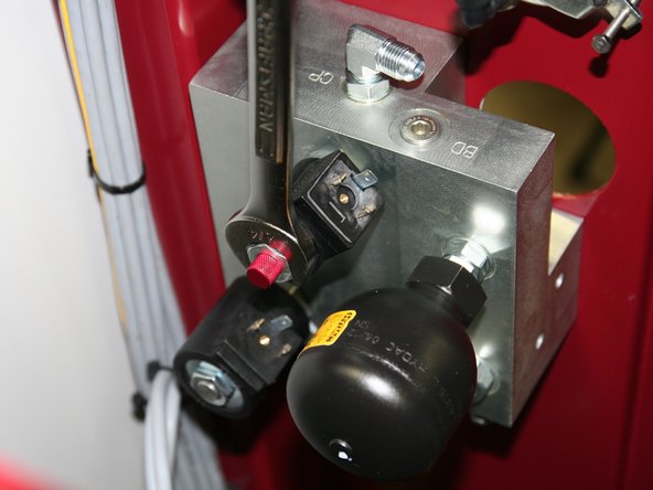
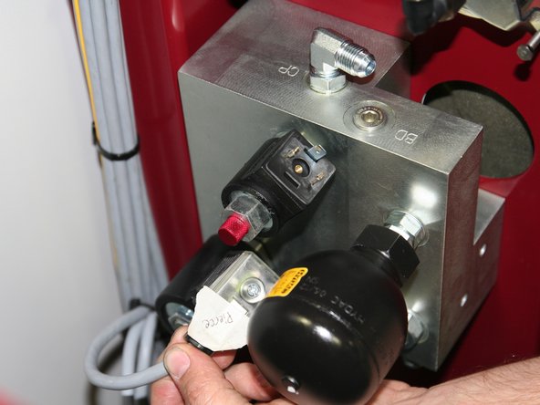
Remove DIN connectors from solenoids on back of old control manifold.
-
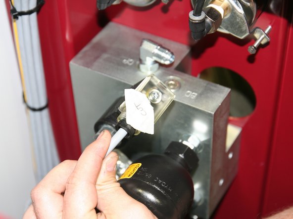
Label DIN connectors "Cut" and "Pierce", respectively, for re-installation.
-
-
-
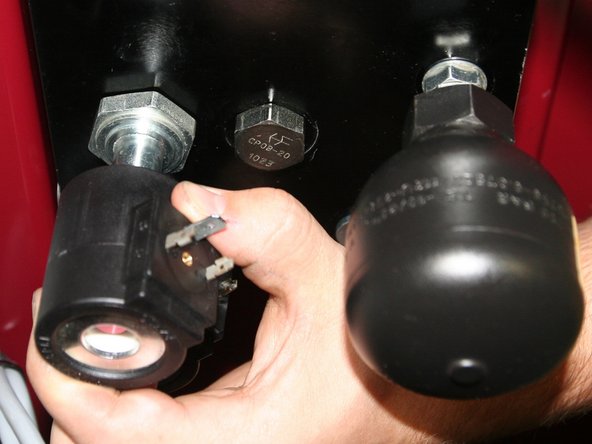
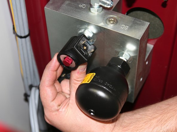
Remove both 24VDC coils from solenoids on back of old control manifold.
-
-
-
Remove old control manifold from pump frame.
-
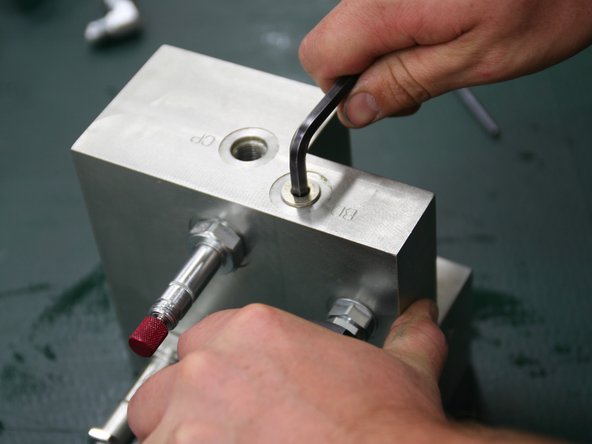
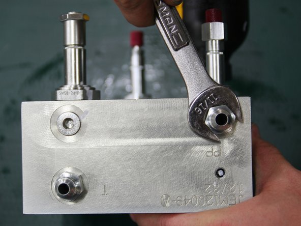
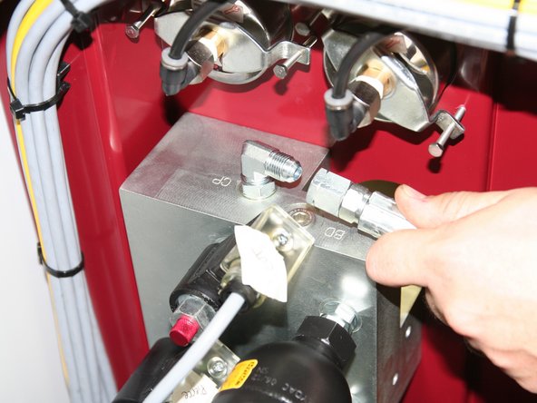
Install plug (6MBP) into port stamped BD on top of new manifold.
-
-
-
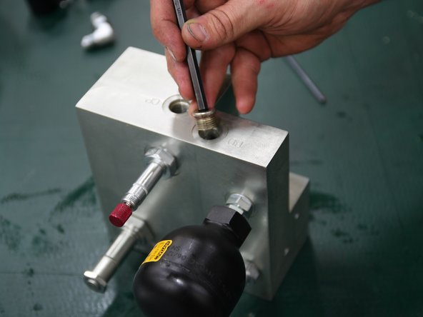
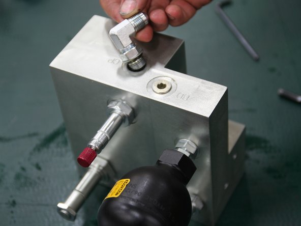
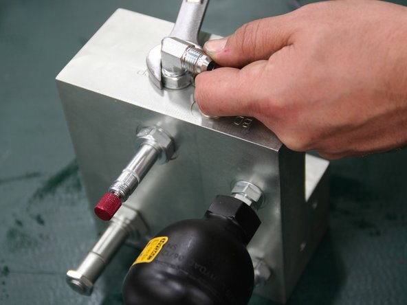
Install 90° fitting (6MJ-6MB90) into port stamped CP on top of new manifold.
-
Be sure to have fitting facing towards pressure gauge port as shown in picture.
-
-
-
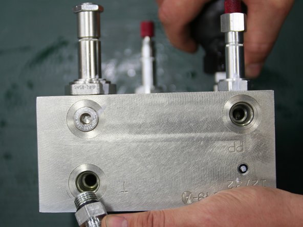
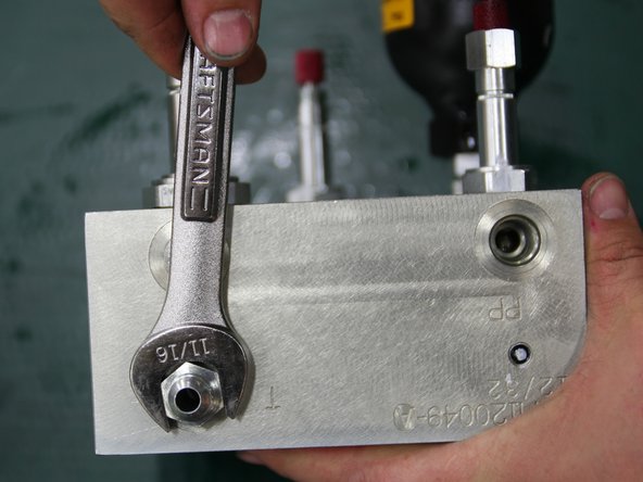
Install straight fittings (removed from old manifold) into ports, labeled T and PP, on bottom of new manifold.
-
Install large 24VDC coil (removed from old manifold) onto large solenoid stem of control manifold.
-
-
-
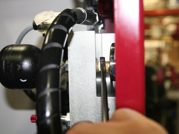
Install new manifold onto pump frame.
-
Use medium strength thread lock on fasteners.
-
-
-
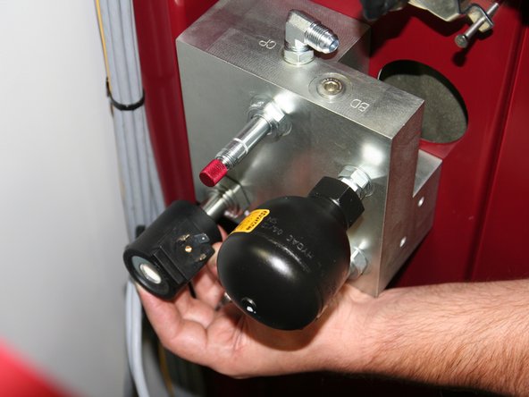
Install large 24VDC coil (removed from old manifold) onto large solenoid stem of control manifold.
-
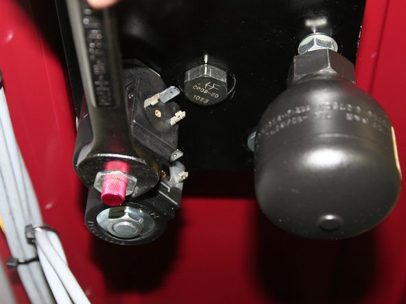
Install small 24VDC Coil (12586) onto small solenoid stem above large stem and beside bullet accumulator.
-
Solenoid directly below oil accumulator (black bulb) is not used in this application.
-
-
-
Reinstall DIN connectors to respective coils as shown in pictures.
-
Tighten DIN connectors to coils.
-
-
-
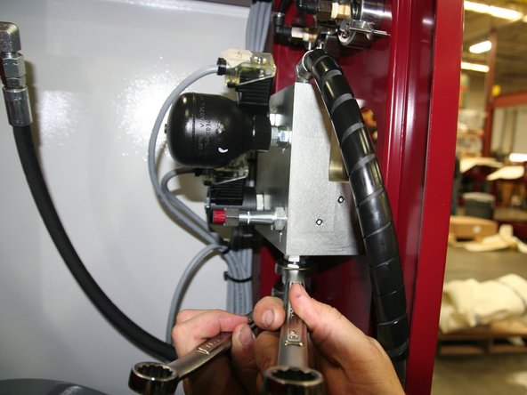
Connect short hydraulic line from "T" fitting near tank to port labeled T on bottom of new manifold.
-
Connect hydraulic line from "T" fitting on hydraulic pump to port labeled PP on bottom of new manifold.
-
-
-
Connect hydraulic line from compensator on pump to port labeled CP on top of new manifold.
-
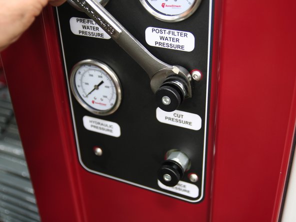
Install pressure gauge in new manifold.
-
Use pipe tape and dope on gauge threads to prevent leaks.
-
-
-
Install control knobs "Cut" and "Pierce" into respective ports on front of manifold.
-
-
-
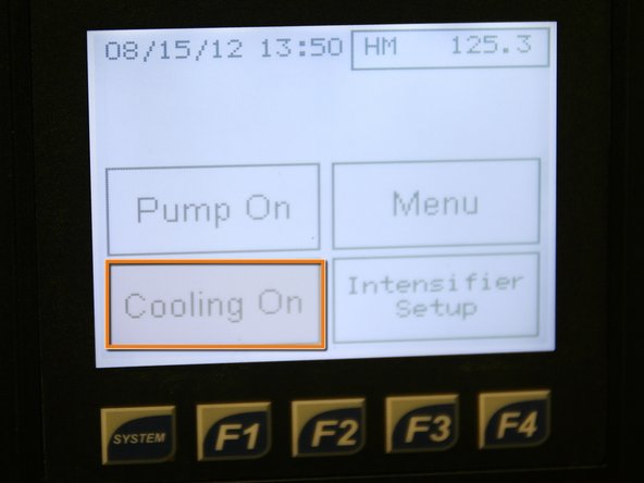
Turn pump on in cooling mode (Cooling On) to allow oil to cycle and re-fill hydraulic lines and manifold.
-
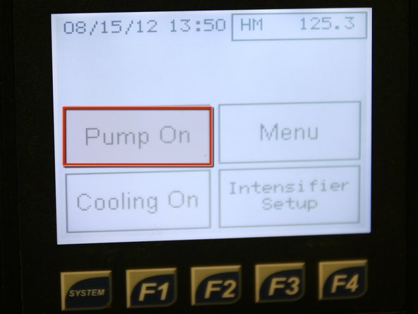
Turn pump on in run mode (Pump On) and verify that "Cut" and "Pierce" control knobs function correctly.
-
Pump is now ready to continue cutting process.
-


Cancel: I did not complete this guide.
One other person completed this guide.