
Introduction
Hypertherm is in no way affiliated with the above mentioned manufacturer
Parts
- Seal Hoop #11323 (included in kit)
- Needle #11322 (included in kit)
- Seal #11321 (included in kit)
- Bushing #11324 (included in kit)
- High-Vacuum Grease #11447 (included in kit)
- Oil Seal #11359 (included in kit)
- Seat #11325 (included in kit)
- O-ring #12880-908 (included in kit)
- O-ring #12880-912 (included in kit)
- O-ring #11679-114 (included in kit)
- O-ring #11680-114 (included in kit)
- Piston Assembly #11778
- Actuator Housing #11779
- Valve Body #11594
- Outlet Adapter #11742
- Collar #13157-60-6
- Mounting Collar #11780
- 3/8" to 1/4" Adapter #11394
- Blue Goop #11111
- O-ring Lube #13969
- Isopropyl Alcohol
-
-
Always make sure that all high-pressure water has been removed from the valve by following the machine manufacturers' safety instructions. Failure to do so can cause severe injury or death.
-
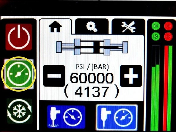
Turn OFF all hydraulic and water pressure to the bleed-down valve.
-
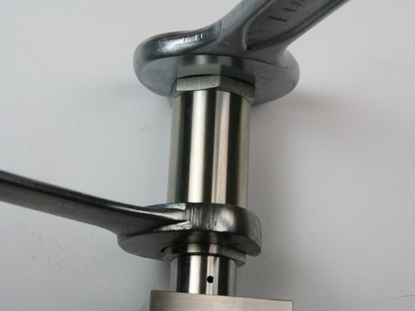
Loosen the hydraulic hose from the hydraulic fitting using a 7/8" and 3/4" wrench.
-
-
-
Unthread the hydraulic hose from the hydraulic fitting.
-
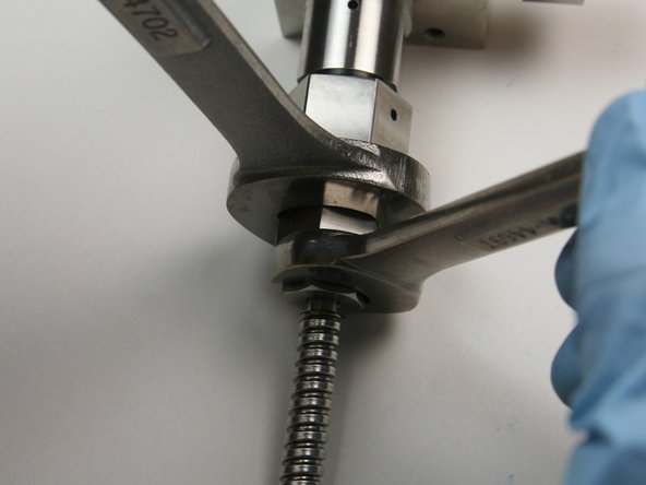
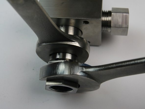
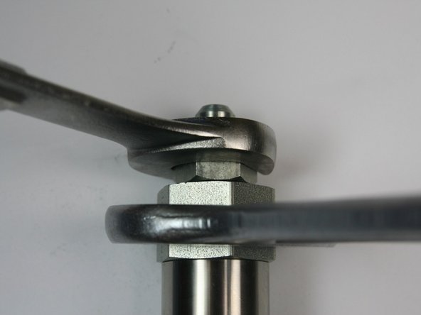
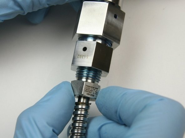
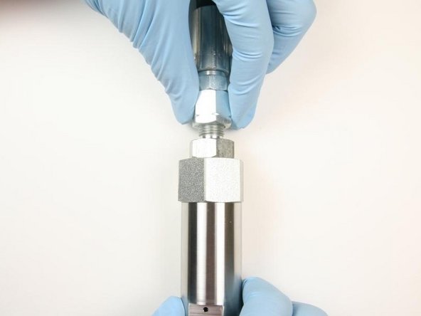
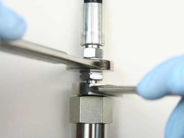
Loosen the gland nut on the high-pressure tubing at the high-pressure inlet port of the bleed-down valve using a 13/16" and 5/8" wrench.
-
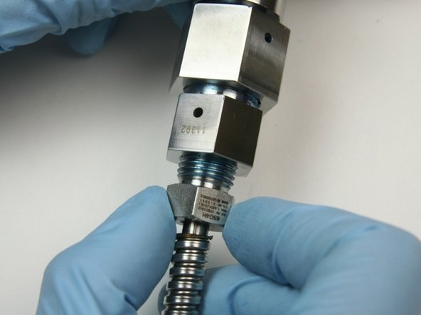
Unthread the gland nut from the outlet fitting at the high-pressure inlet port of the bleed-down valve.
-
-
-
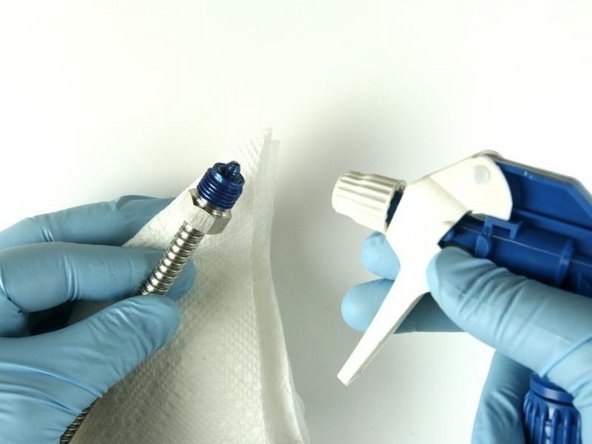
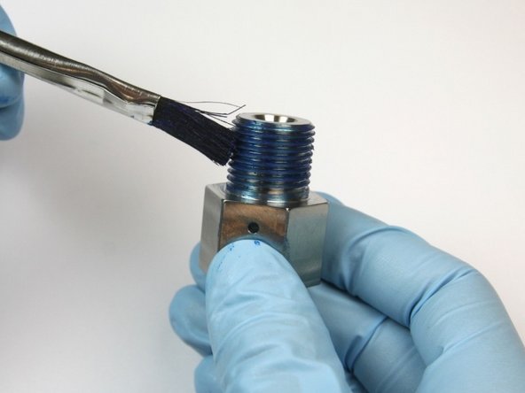
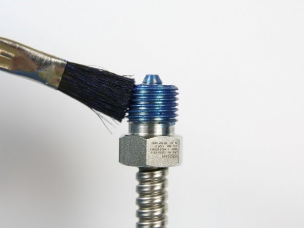
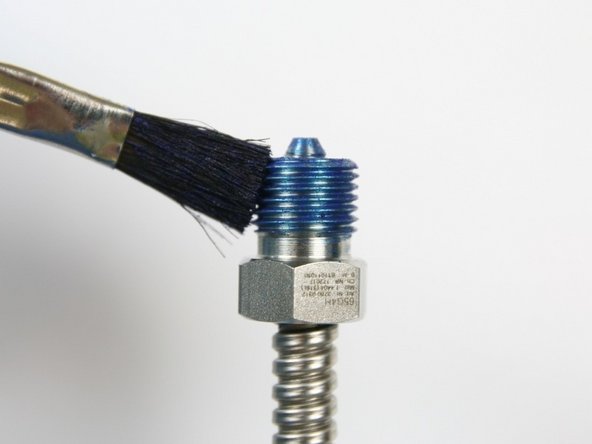
Clean the gland nut of all Blue Goop with isopropyl alcohol or a similar cleaning agent.
-
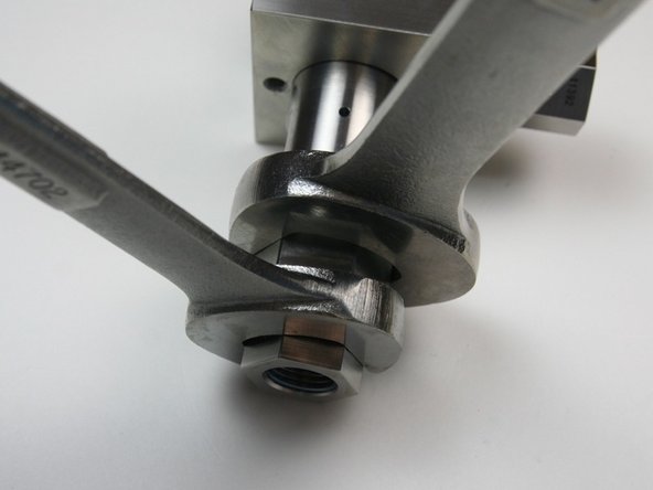
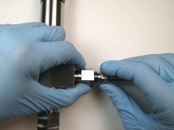
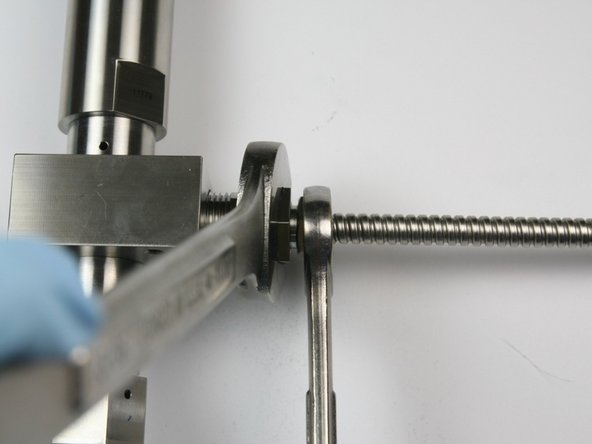
Loosen the gland nut from the outlet fitting (connected to the valve body) using a 13/16" and 5/8" wrench.
-
Unthread the gland nut from the outlet fitting (connected to the valve body).
-
-
-
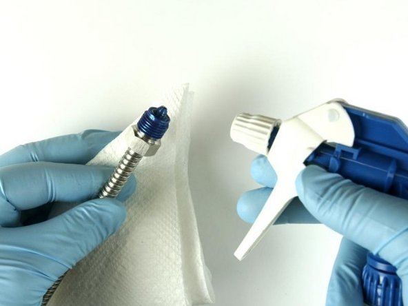
Clean the gland nut of all the Blue Goop.
-
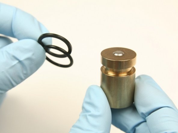
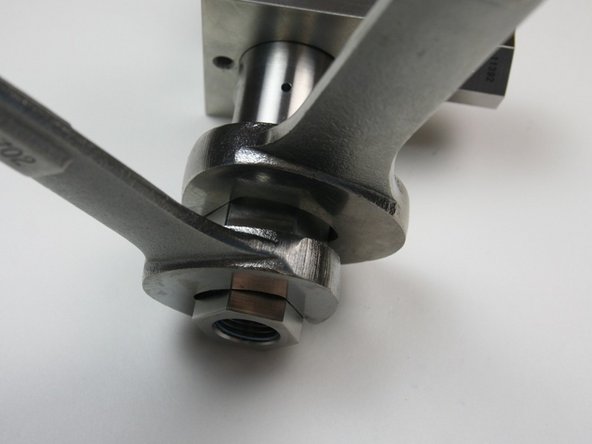
Loosen the hydraulic fitting from the adapter fitting using a 1-1/4" and 7/8" wrench.
-
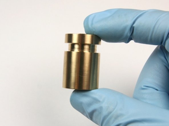
Unthread the hydraulic fitting from the adapter fitting.
-
-
-
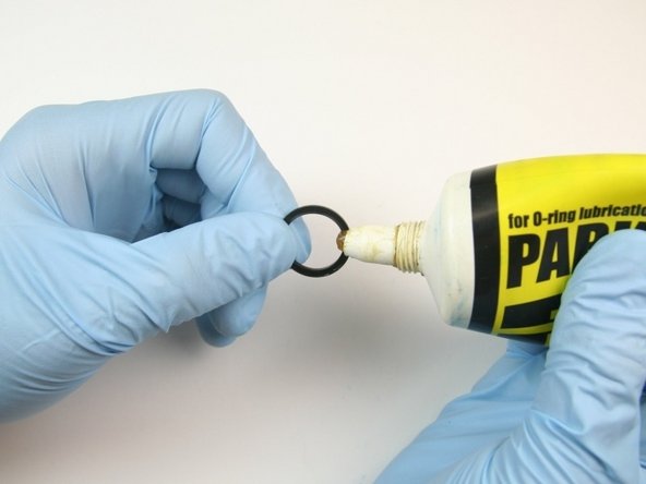
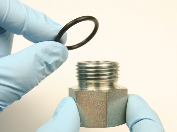
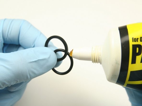
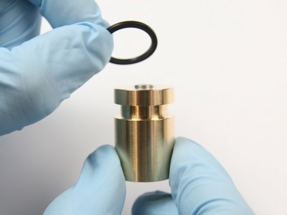
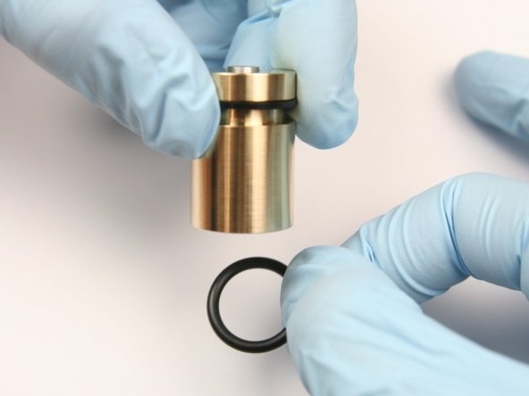
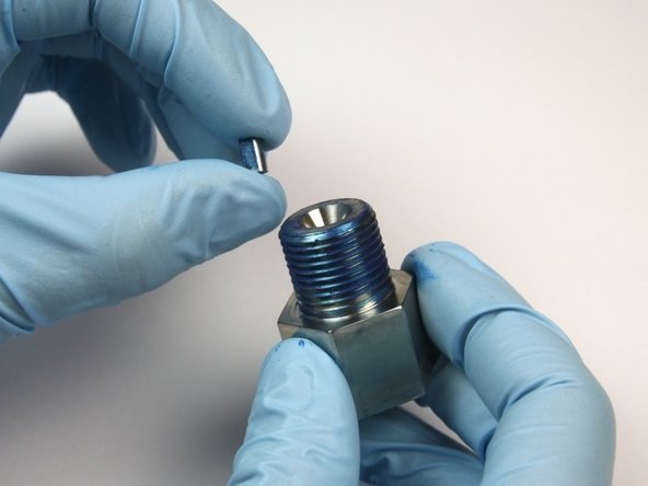
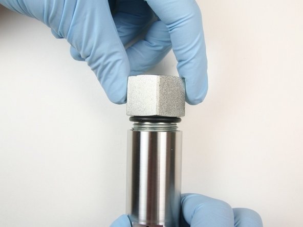
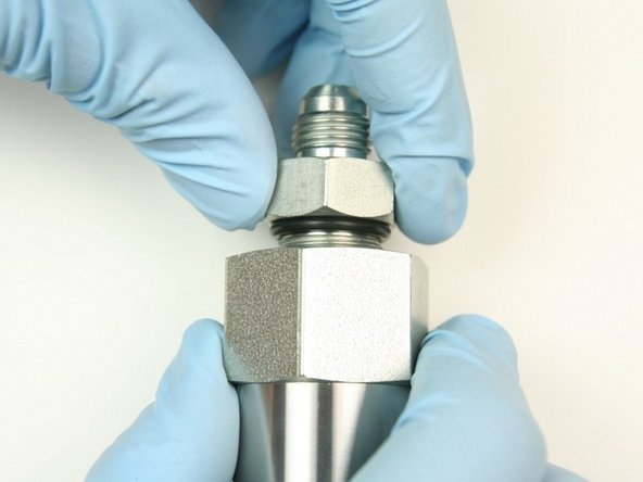
Apply an O-ring lubricant to the O-ring from the kit for the hydraulic fitting.
-
Replace the O-ring around the hydraulic fitting with the O-ring from the kit (the smallest O-ring from the kit).
-
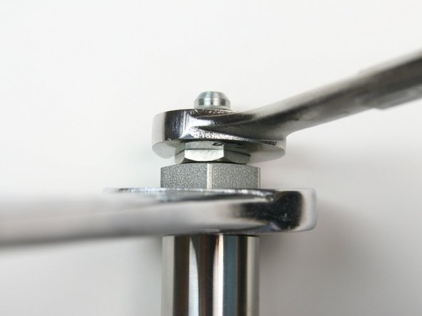
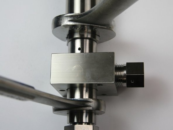
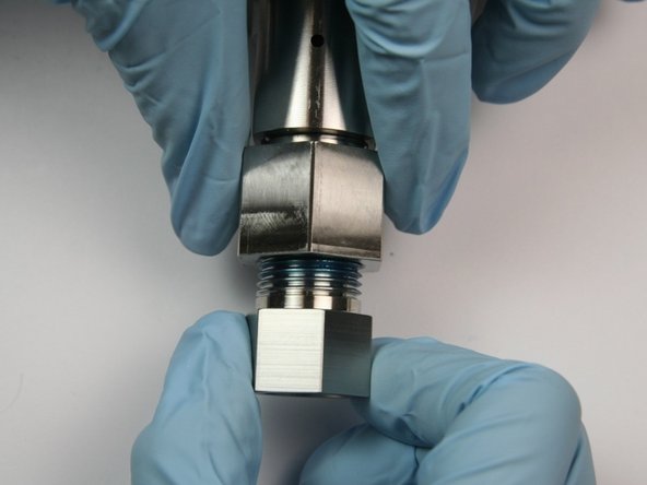
Loosen the adapter fitting from the actuator housing using a 1-1/4" and 1-1/16" wrench.
-
-
-
Unthread the adapter fitting from the actuator housing.
-
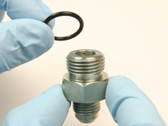
Apply an O-ring lubricant to the largest O-ring from the kit.
-
Replace the O-ring on the adapter fitting with the largest O-ring from the kit.
-
-
-
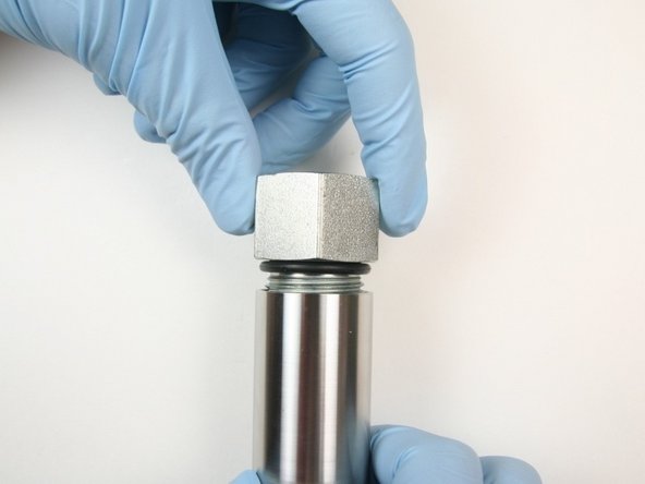
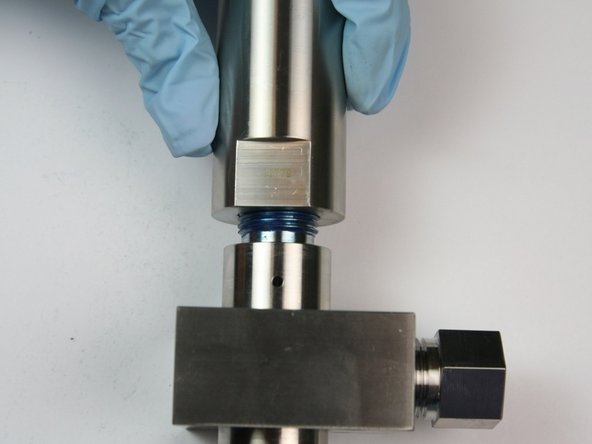
Loosen the actuator housing from the valve body using a 1-1/16" and 7/8" wrench.
-
Unthread the actuator housing from the valve body.
-
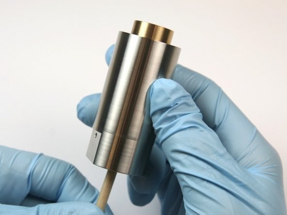
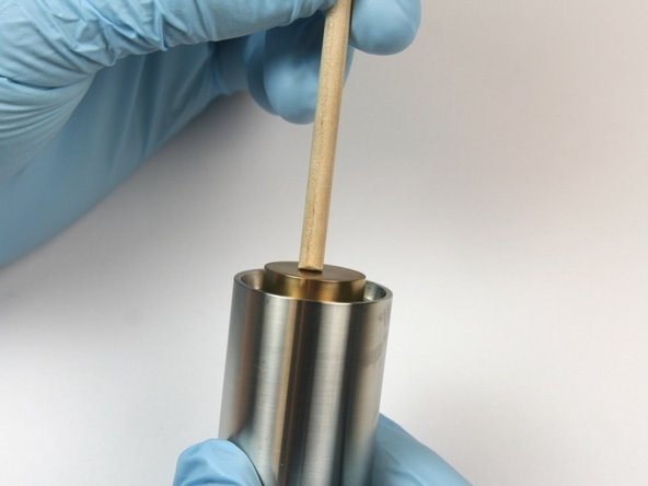
Push the piston out of the actuator housing through the oil port using the included dowel.
-
-
-
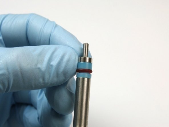
Discard the O-ring and the back-up ring from the piston.
-
Inspect the piston, if damage is visible, replace.
-
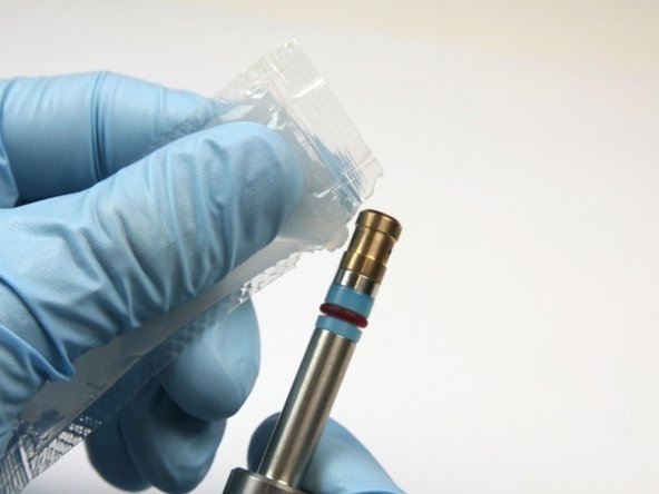
Apply an O-ring lubricant to cover all of the O-ring and the back-up ring.
-
-
-
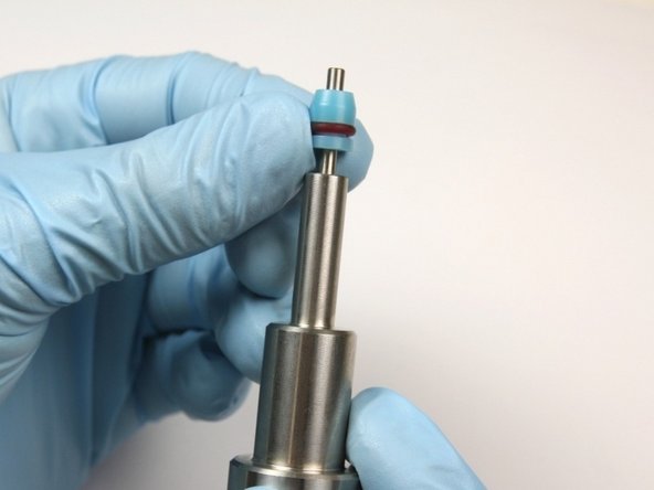
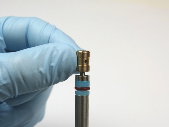
Slide the new back-up ring (flat) to the groove of the piston.
-
Slide the new O-ring (rounded) to the groove of the piston.
-
Make sure the concave side of the back-up ring is towards the O-ring.
-
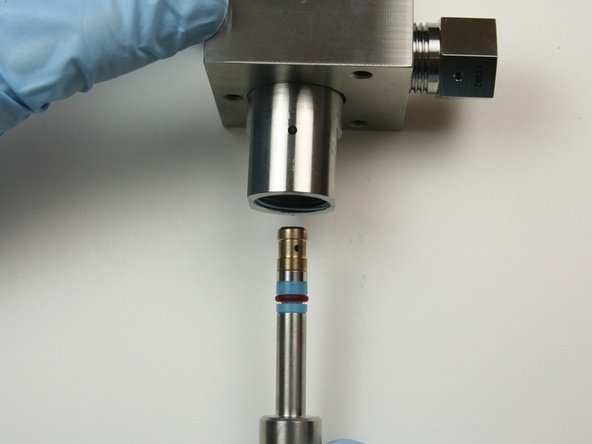
Put the piston assembly into the actuator housing the the groove side first and push the piston with the included dowel until the piston bottoms out.
-
-
-
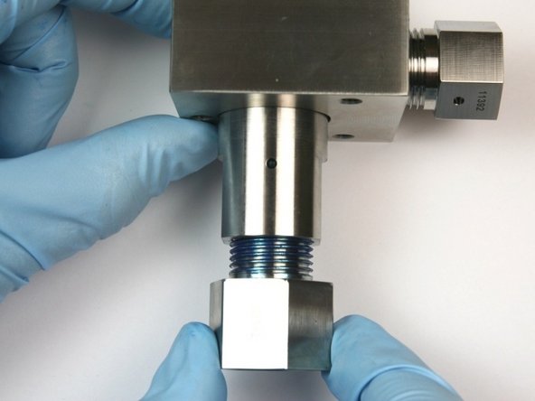
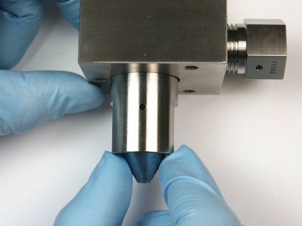
Loosen the 3/8" to 1/4" adapter from the outlet fitting using a 7/8" and 13/16" wrench.
-
Unthread the 3/8" to 1/4" adapter from the outlet fitting.
-
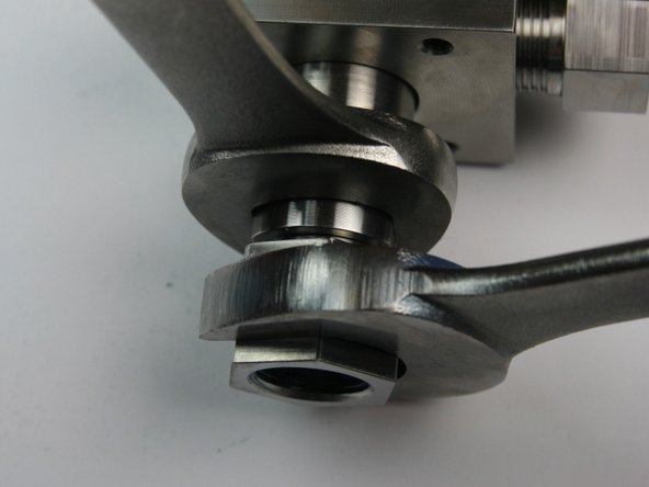
Loosen the outlet fitting from the bleed down valve body using a 7/8" and 13/16" wrench.
-
-
-
Unthread the outlet fitting from the bleed down valve body.
-
Remove the high-pressure seat from the bleed down valve body.
-
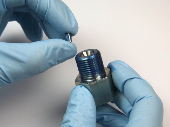
Remove the flow reducer from the outlet adapter.
-
-
-
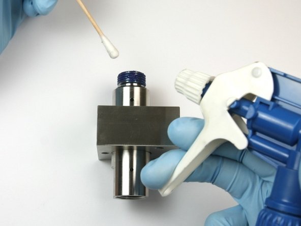
Clean the outlet adapter of all the Blue Goop.
-
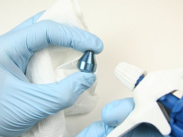
Clean the high-pressure seat of all the Blue Goop.
-
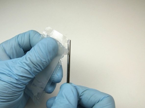
With the bleed down valve tool push through the bleed-down valve body to remove all components.
-
The oil seal can also be removed by the bleed down valve tool.
-
-
-
Thoroughly clean the valve body before replacing the components.
-
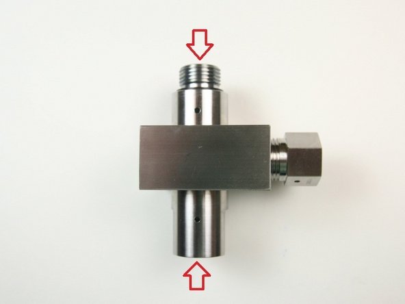
Visually inspect the top/bottom of the valve body, if excessive wear or cracks are visible, replace the valve body.
-
Put the high-pressure seal on to the bleed-down valve tool with the O-ring towards the bleed down valve tool.
-
-
-
Slide the hoop, with the sharp edge first, on to the bleed-down valve tool behind the high-pressure seal.
-
Slide the bushing on the bleed-down valve tool with the chamfer side away from the hoop.
-
Apply a high-pressure lubricant to the high-pressure seal, hoop, and bushing.
-
The O-ring on the high-pressure seal can pinch or strip when installing into the valve body.
-
-
-
Put the bleed-down valve tool with the parts into the bottom of the valve body until the tool reaches the bottom of the valve.
-
Be aware that the inner diameter of the valve body has a small step, it can pinch or strip the O-ring from the high-pressure seal during installation.
-
Apply a high-pressure lubricant to the stem.
-
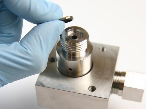
Replace the oil seal, place on the top of the valve body.
-
Put the concave (rubber) side down towards the valve body.
-
-
-
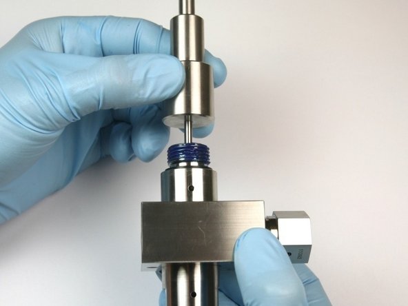
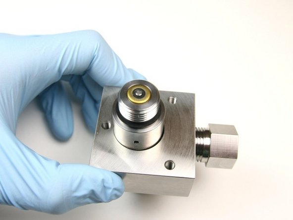
Put the stem through the high-pressure seal until it is flush with the oil seal.
-
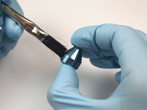
Apply Blue Goop to all surfaces of the high-pressure seat.
-
Put the high-pressure seat at the bottom of the bleed-down valve body with the pointed end out.
-
-
-
Apply Blue Goop to the outlet adapter threads.
-
Put the flow reducer in the outlet adapter.
-
Thread the outlet adapter into the valve body.
-
-
-
Tighten the outlet adapter to the valve body using a 7/8" and 13/16" wrench.
-
Thread the 3/8" to 1/4" adapter to the outlet adapter.
-
Tighten the 3/8" to 1/4" adapter to the outlet adapter using a 7/8" and 13/16" wrench.
-
-
-
Apply Blue Goop to the top threads of the valve body.
-
With the piston assembly installed, thread the actuator housing onto the valve body.
-
Tighten the actuator housing to the valve body using 1-1/16" and 7/8" wrench.
-
-
-
Thread the adapter fitting into the actuator housing.
-
Tighten the adapter fitting into the actuator housing using 1-1/4" and 1-1/16" wrench
-
Thread the hydraulic adapter into the adapter fitting.
-
-
-
Tighten the hydraulic fitting into the adapter fitting using 1-1/4" and 7/8" wrench.
-
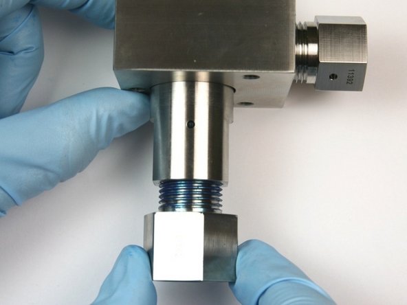
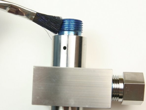
Apply Blue Goop to the threads of the gland nut.
-
Thread the gland nut into the outlet fitting (connected to the valve body).
-
-
-
Tighten the gland nut to the outlet fitting (connected to the valve body) using 13/16" and 5/8" wrench.
-
Apply Blue Goop to the gland nut threads.
-
Thread the gland nut into the outlet fitting (connected to the collar).
-
-
-
Tighten the gland nut into the outlet fitting (connected to the collar) using a 13/16" and 5/8" wrench.
-
Thread the hydraulic hose on to the hydraulic fitting.
-
Tighten the hydraulic hose to the hydraulic fitting using a 7/8" and 3/4" wrench.
-
-
-
Turn the pump ON and continue the cutting process.
-


Cancel: I did not complete this guide.
4 other people completed this guide.