
Tools
Parts
- Bleed Down Valve Body II #12943
- Bleed Down Valve Needle II #12942
- Bleed Down Valve High-Pressure Seal #11321
- Bleed Down Valve Seal Hoop #11323
- Bleed Down Valve Stem Bushing #11324
- Poppet Seat #11141
- Seal Back-up Screw #12945
- Outlet Adapter #12944
- Flow Reducer #11743
- Bleed Down Valve Housing Body #11779
- Bleed Down Valve Hydraulic Piston #11778
- Back-up O-ring #11680-114
- Male to Female Hydraulic Adapter #11796
- O-ring SAE #12880-912
- O-ring Lube #13969
- High Vacuum Grease #11447
- Blue Goop #11111
- Isopropyl Alcohol
-
-
Always make sure all high-pressure water has been removed from the valve by following the machine manufacturers' safety instructions. Failure to do so can cause severe injury or death.
-
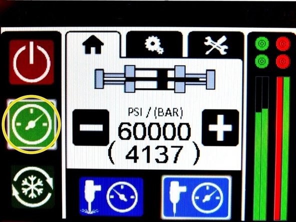
Turn OFF all hydraulic and water pressure to the bleed-down valve.
-
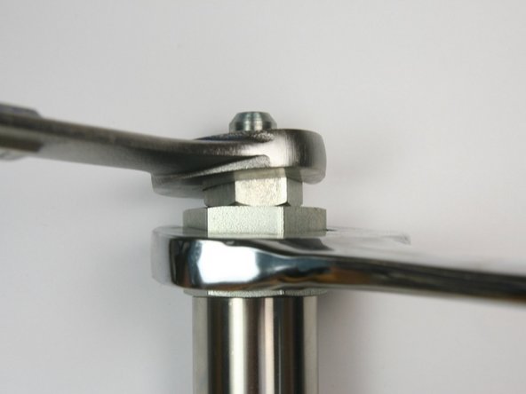
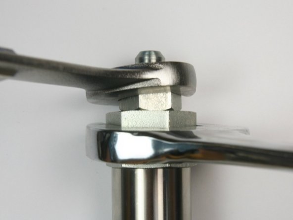
Loosen the hydraulic hose from the hydraulic fitting using 7/8" and 3/4" wrench.
-
-
-
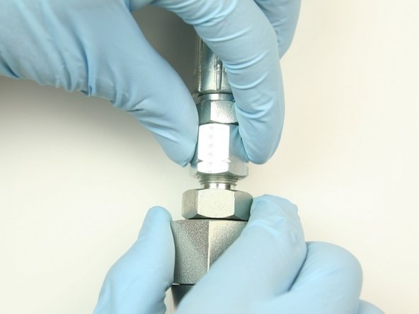
Unthread the hydraulic hose from the hydraulic fitting.
-
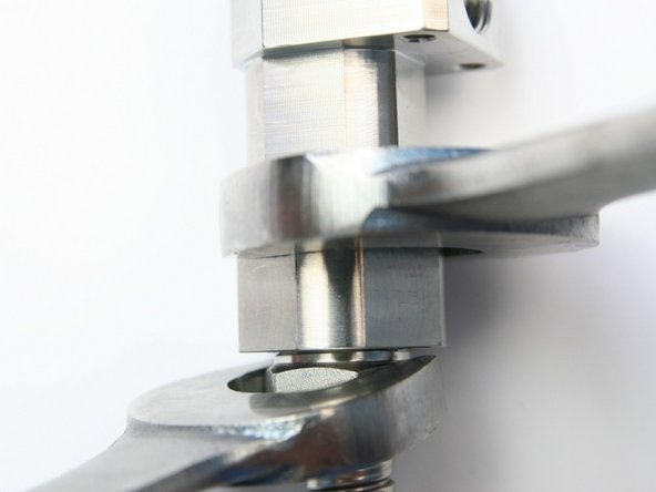
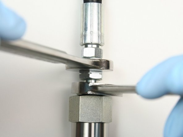
Loosen the 1/4" gland nut from the side inlet of the valve body.
-
Unthread the 1/4" gland nut from the side inlet of the valve body.
-
-
-
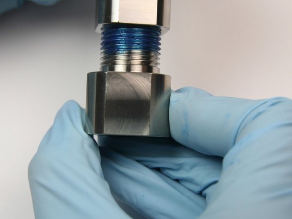
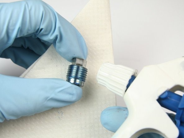
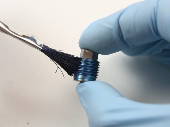
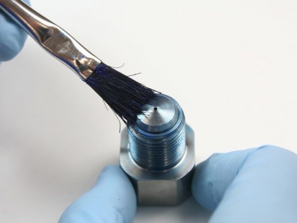
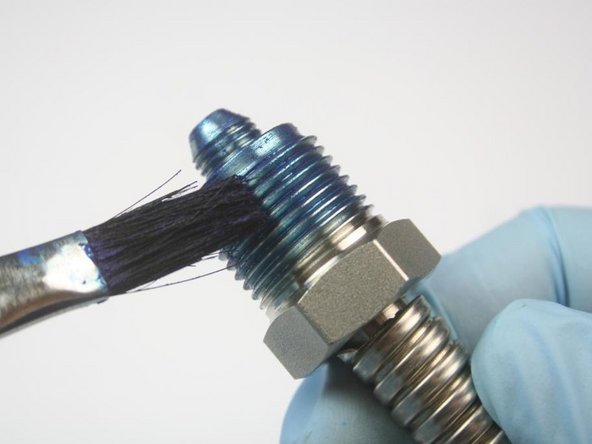
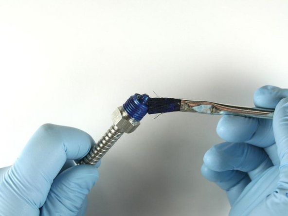
Clean the 3/8" gland nut of all Blue Goop with isopropyl alcohol.
-
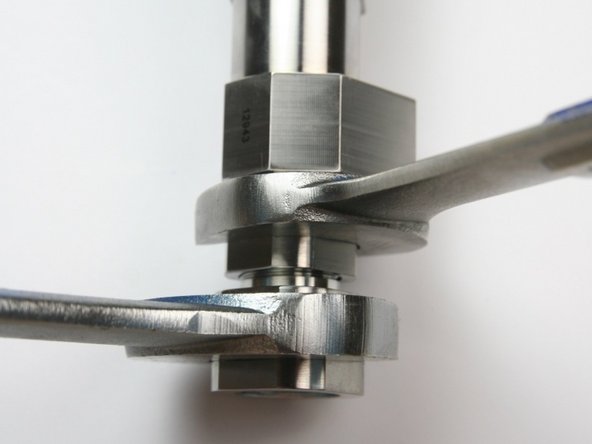
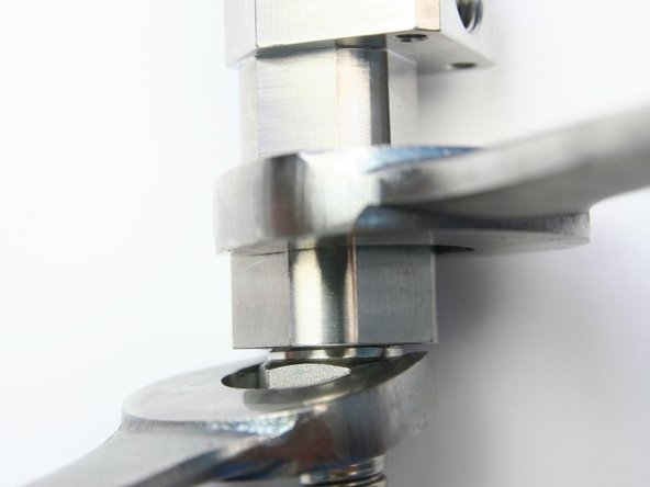
Loosen the 3/8" high-pressure gland from the outlet adapter using 13/16" and 1" wrench.
-
Unthread the 3/8" high-pressure gland from the outlet adapter.
-
-
-
Clean the 3/8" gland nut of all Blue Goop with isopropyl alcohol.
-
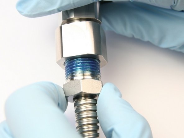
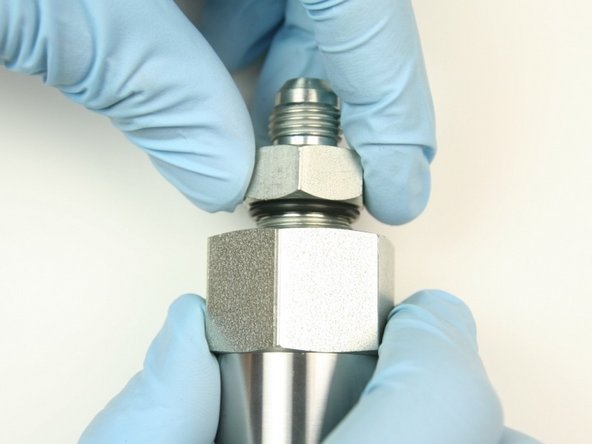
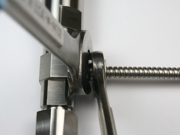
Loosen the hydraulic fitting from the adapter fitting using 1-1/4" and 7/8" wrench.
-
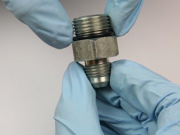
Unthread the hydraulic fitting from the adapter fitting.
-
-
-
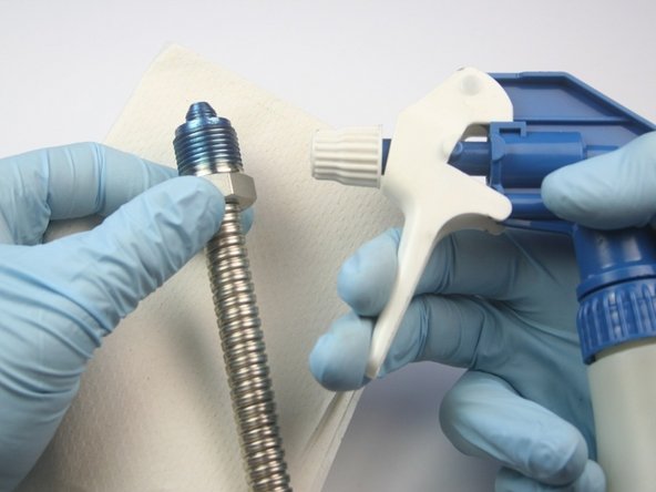
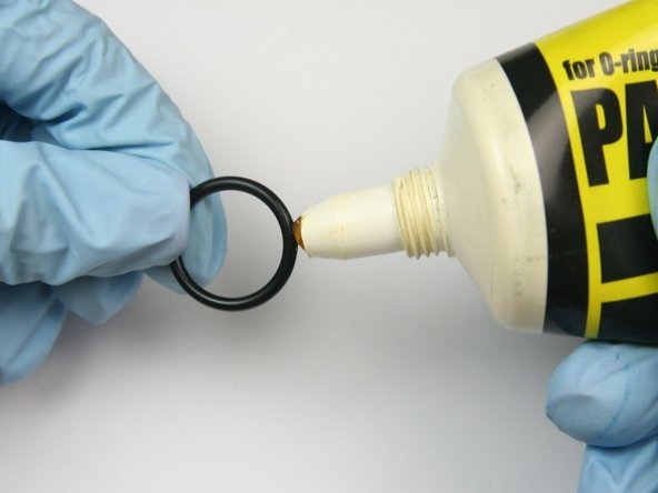
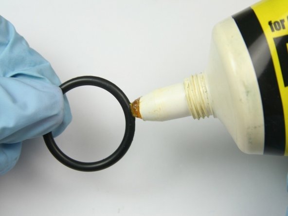
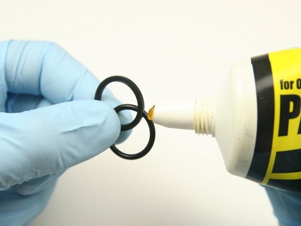
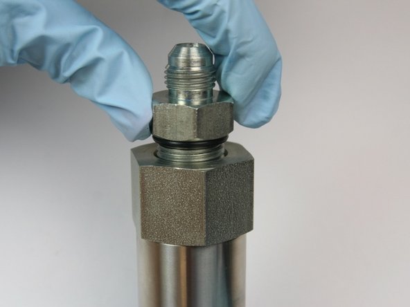
Apply an O-ring lubricant to the O-ring from the kit for the hydraulic fitting.
-
Replace the O-ring on the hydraulic fitting with the O-ring from the kit (smallest O-ring in kit).
-
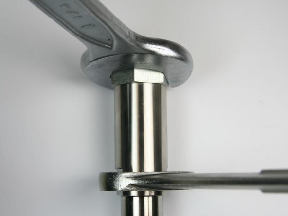
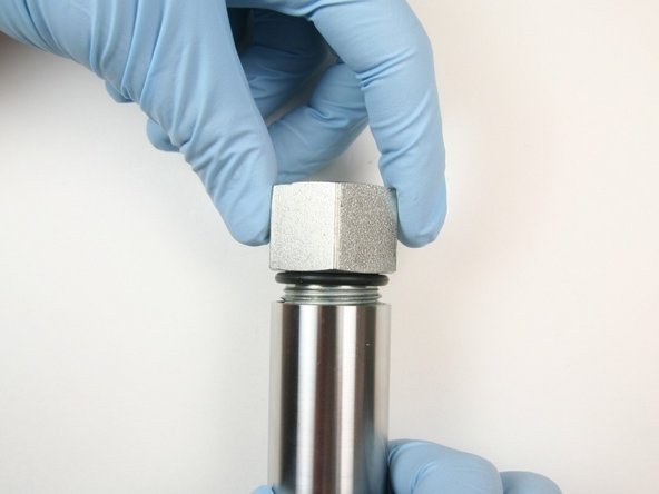
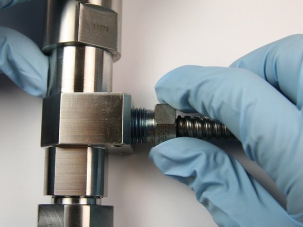
Loosen the adapter fitting from the actuator housing using 1-1/4" and 1-1/16" wrench.
-
-
-
Unthread the adapter fitting from the actuator housing.
-
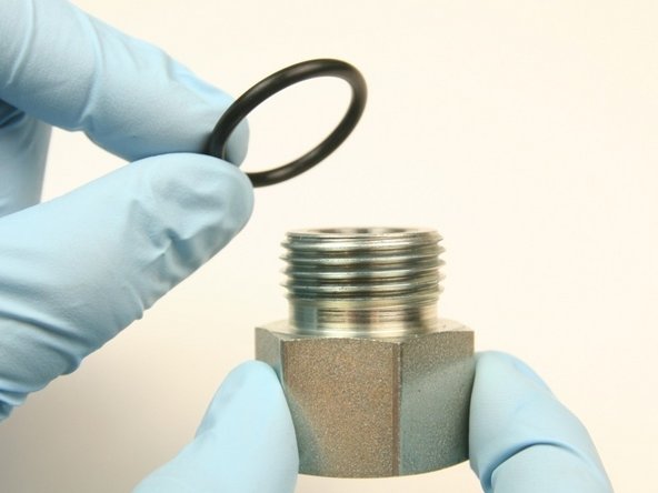
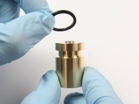
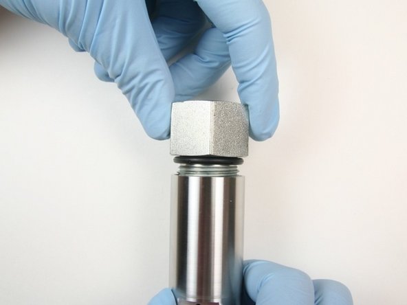
Apply an O-ring lubricant to the largest O-ring from the kit.
-
Replace the O-ring on the adapter fitting with the largest O-ring from the kit.
-
-
-
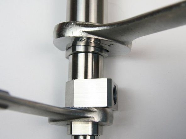
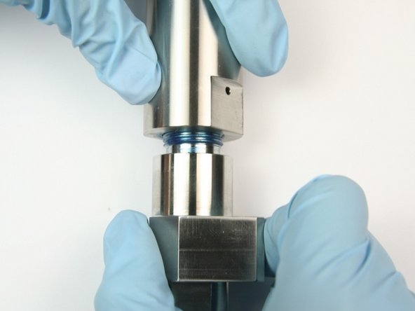
Loosen the actuator housing from the valve body using 1-1/16" and 7/8" wrench.
-
Unthread the actuator housing from the valve body.
-
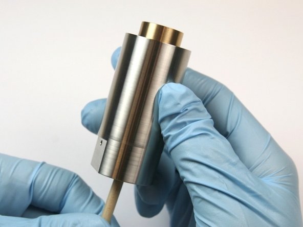
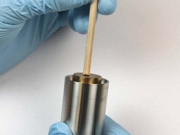
Push the piston out of the actuator housing through the oil port using the included dowel.
-
-
-
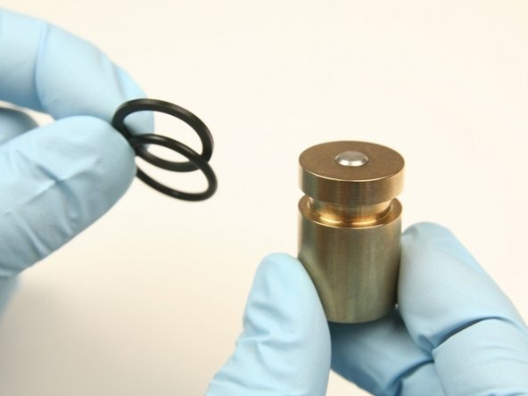
Discard the O-ring and back-up ring from the piston.
-
Inspect the piston, if damage is visible, replace.
-
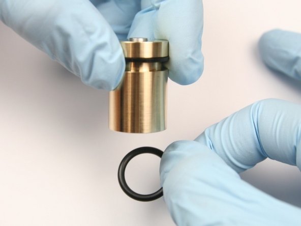
Apply an O-ring lubricant to the O-ring and back-up ring.
-
-
-
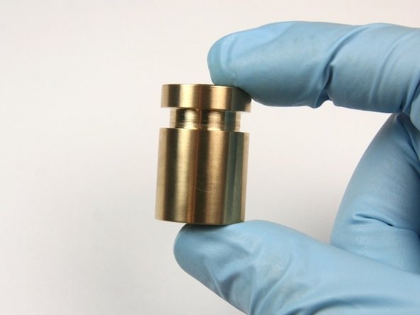
Slide the new back-up ring (flat) into the groove of the piston.
-
Make sure the concave side of the back-up ring is towards the O-ring.
-
Slide the new O-ring (rounded) into the groove of the piston.
-
Put the piston assembly into the actuator housing and push with the included dowel.
-
-
-
Loosen the outlet fitting from the bleed down valve body using 7/8" and 13/16" wrench.
-
Unthread the outlet fitting from the bleed down valve body.
-
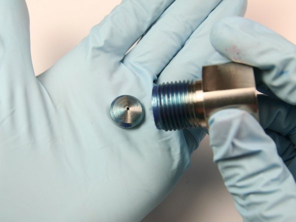
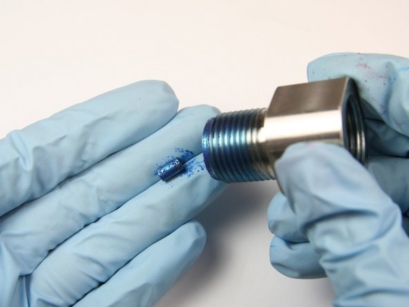
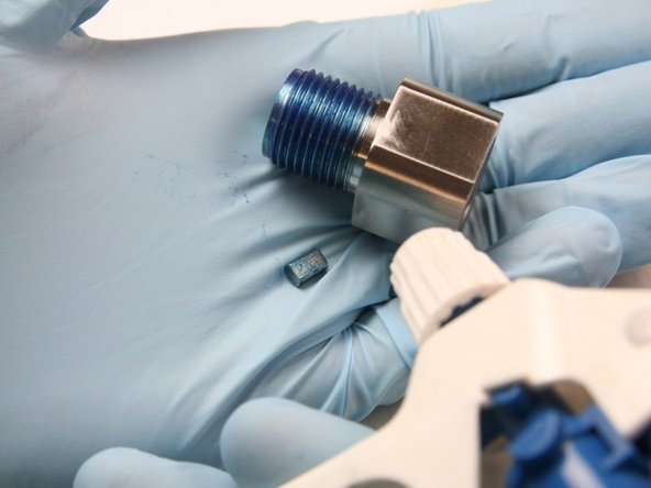
Remove the high-pressure seat from the bleed down valve body and discard.
-
-
-
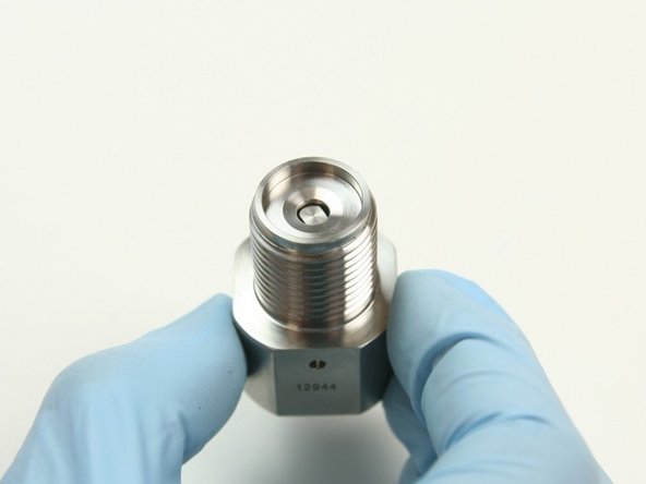
Remove theflow reducer from the outlet adapter.
-
Clean the outlet adapter and the flow reducer of all Blue Goop with isopropyl alcohol.
-
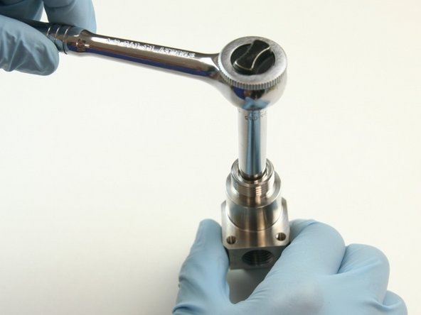
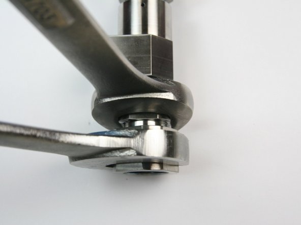
Loosen the back-up screw from the top of the bleed down valve body using a 5/16" socket wrench.
-
-
-
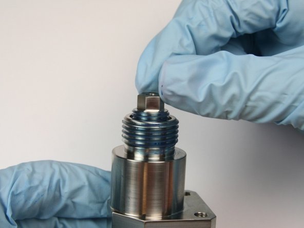
Unthread the seal back-up screw from the top of the bleed down valve body.
-
Clean the seal back-up screw with isopropyl alcohol.
-
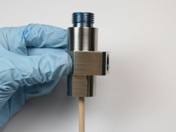
Push the components through the bleed down valve body with the included dowel.
-
-
-
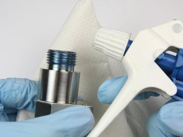
Clean the bleed down valve body with isopropyl alcohol or a similar cleaning agent.
-
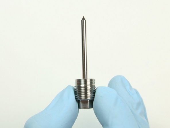
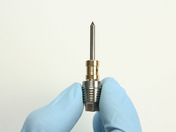
Apply ahigh vacuum grease to the needle.
-
Slide the back-up screw on to the needle so the flat end of the needle is flush with the non threaded part of the back-up screw.
-
-
-
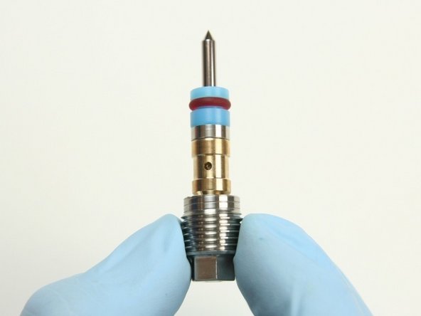
Slide the bushing onto the point of the needle with the chamfered end towards the back-up screw.
-
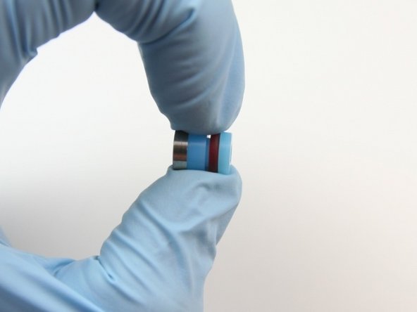
Put the hoop onto the high-pressure seal with the tapered end towards the high-pressure seal and opposite from the O-ring.
-
Put the high-pressure seal assembly onto the point of the needle with the hoop, first.
-
-
-
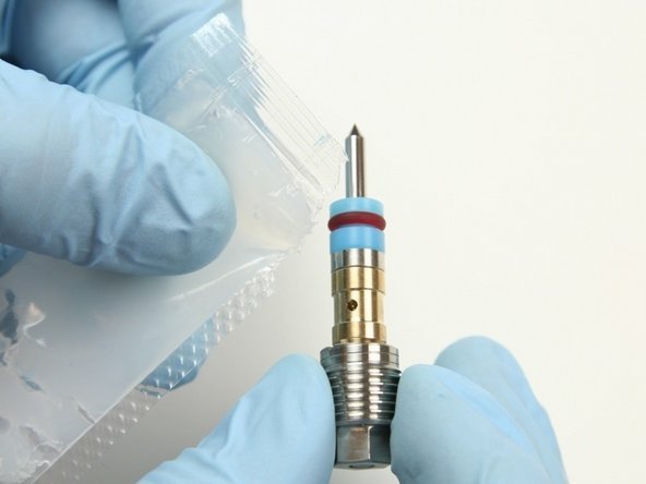
Apply a high vacuum grease to the exterior of the high-pressure seal, hoop, and bushing.
-
Apply a high vacuum grease to the internal threads of the bleed down valve body.
-
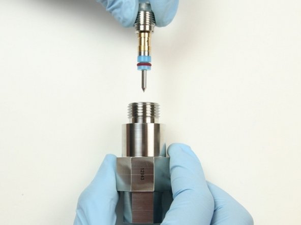
Put the high-pressure needle assembly into the top of the bleed down valve body with the point first.
-
-
-
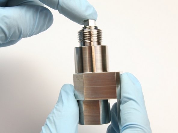
Push the seal back-up screw inside of the valve body until it bottoms out.
-
Take the seal back-up screw out of the body and apply a layer of Blue Goop to the threads.
-
Thread in the back-up screw into the top of the bleed down valve body.
-
-
-
Tighten the back-up screw to the top of the bleed down valve body using a 5/16" socket wrench.
-
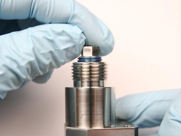
Put the flow reducer into the hole beneath the seat cavity in the outlet adapter.
-
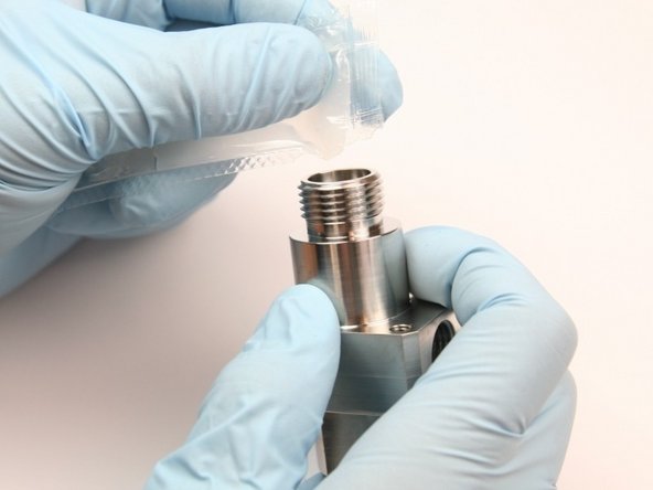
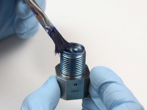
Apply a layer of Blue Goop to the external threads and the seat cavity of the outlet adapter.
-
-
-
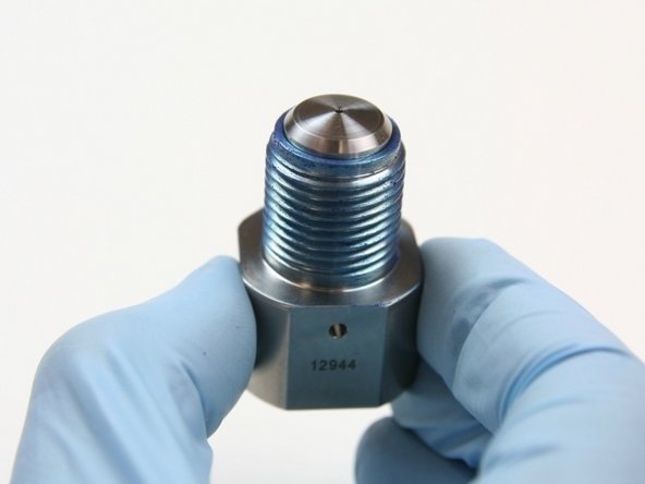
Put the poppet seat into the seat cavity of the outlet adapter.
-
Apply a layer of Blue Goop to the top of the poppet seat that is sitting in the outlet adapter.
-
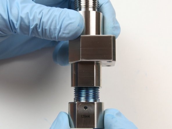
Thread the outlet adapter into the valve body.
-
-
-
Using a 1" wrench on the outlet adapter and a 7/8" wrench on the valve body, tighten together securely.
-
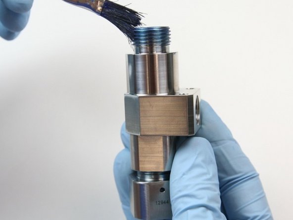
Apply a layer of Blue Goop to the external threads of the valve body.
-
Thread the actuator housing onto the valve body.
-
-
-
Tighten the actuator housing to the valve body using a 1-1/16" and 7/8" wrench.
-
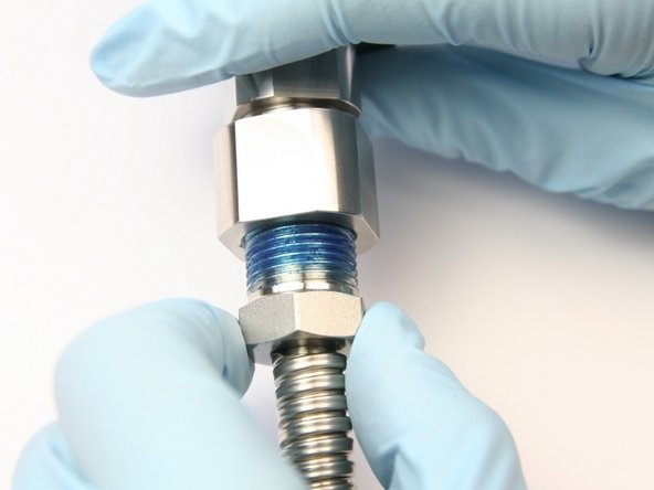
Apply Blue Goop to the 3/8" gland nut threads.
-
Thread the 3/8" gland nut with the high-pressure tubing into the bleed down valve adapter.
-
-
-
Tighten the gland nut into the bleed down valve adapter using 13/16" and 5/8" wrench.
-
Apply Blue Goop to the 1/4" gland nut threads.
-
Thread the 1/4" gland nut into the side of the bleed down valve body.
-
-
-
Tighten the gland nut to the side of the bleed down valve body using 3/4" and 5/8" wrench
-
Thread the adapter fitting into the actuator housing.
-
Tighten the adapter fitting into the actuator housing using 1-1/4" and 1-1/16" wrench.
-
-
-
Thread the hydraulic fitting into the hydraulic adapter.
-
Tighten the hydraulic fitting into the hydraulic adapter.
-
Thread the hydraulic hose onto the hydraulic fitting.
-
-
-
Tighten the hydraulic hose to the hydraulic fitting using 7/8" and 3/4" wrench.
-
Turn the pump ON and continue the cutting process.
-


Cancel: I did not complete this guide.
6 other people completed this guide.
2 Comments
I have a question why the needle
The valve is frequently coated
Horlando Muñiz - Resolved on Release Reply
Hello,
Please visit Hypertherm.com to find the relevant technical service phone number or email address. Our global tech service team will be able to help you with any questions you may have.
Best regards,
Arion Vandergon
Product Marketing Manager - Waterjet